HB9UF Signal Snitch
Zusammenbau-Anleitung und Abstimmung
1. Löte die zwei Batterie-Halter ein.
Es kann helfen, das Teil mit etwas Papier zu unterlegen, um es während dem Löten in Position zu halten.
2. Löte die drei Widerstände gemäss ihren Bauteilwerten ein. Die Orientierung ist hier egal.
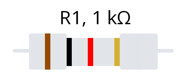
R1 = 1k = 1 kilo-Ohm = Braun, Schwarz, Rot, Gold
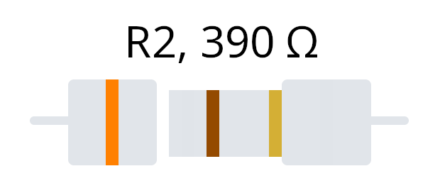
R2 = 390 = 390 Ohm = Orange, Weiss, Braun, Gold
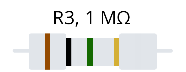
R3 = 1M = 1 Mega-Ohm = Braun, Schwarz, Grün, Gold
3. Löte die 2 Dioden D1 & D2 ein (blau mit schwarzem Ring = Kathode = K).
Achte hier auf die Orientierung!
4. Löte den Kondensator ein.
C1 = 1n = 1 Nanofarad.
Die Orientierung ist hier egal.
5. Löte die 2 Transistoren ein.
Achtung: Die beiden Transistoren sind unterschiedlich. Achte auf die Orientierung der flachen Stelle!
Q1: J211
Q2: BC559
6. Löte das Potentiometer (Pot 1 10k) ein.
Die Orientierung ist hier tatsächlich egal. Empfohlen ist, die Einstellschraube gegen innen (weg vom Platinenrand) zu haben.
7. Löte die LED ein.
Achte auf die Einbaurichtung, das Lötloch für das längere der 2 Beine ist beschriftet.
Abstimmung
Lege die zwei CR2032 Knopfzellen ein, und drehe das Potentiometer mit einem Schraubenzieher, bis die LED nur schwach leuchtet. Gehe anschliessend zum CubeSat und beobachte, wie die LED zu leuchten beginnt.
Du kannst auch dein Handy neben den Signal Snitch legen und den Flugmodus ein- und wieder ausschalten. Dabei versendet dein Handy Daten, welche LED-Flackern angezeigt werden.
Sollte die LED wenig oder selten leuchten, dann drehe vorsichtig an der Einstellschraube des Potentiometers bis sie Signale zuverlässig anzeigt.
Assembly Instructions and Adjustment
1. Solder the two battery holders.
It can help to place a piece of paper underneath to hold the part in position while soldering.
2. Solder the three resistors according to their component values.
The orientation does not matter here.
R1 = 1k = 1 kilo-Ohm = Brown, Black, Red, Gold
R2 = 390 = 390 Ohm = Orange, White, Brown, Gold
R3 = 1M = 1 Mega-Ohm = Brown, Black, Green, Gold
3. Solder the two diodes D1 and D2.
(blue with a black ring = cathode = K).
Pay attention to the orientation!
4. Solder the capacitor.
C1 = 1n = 1 Nanofarad.
The orientation does not matter here.
5. Solder the two transistors.
The two transistors are of different types. Pay attention to the orientation of the flat side!
Q1: J211
Q2: BC559
6. Solder in the potentiometer (Pot 1, 10k).
The orientation actually doesn’t matter here. It is recommended to position the adjustment screw away from the edge of the circuit board.
7. Solder the LED.
Pay attention to the orientation; the solder hole for the longer of the two legs is marked.
Calibration:
Insert the two CR2032 button cells and turn the potentiometer with a screwdriver until the LED only glows faintly. Then move the unit close to the CubeSat and observe how the LED turns on.
You can also place your cellphone next to the Signal Snitch and switch airplane mode on and off. In doing so, your phone will transmit data, which is indicated by flickering of the LED.In doing so, your phone will transmit data, which the "Signal-Snitch" should indicate by flickering the LED.
If the LED lights up weakly or rarely, carefully turn the adjustment screw of the potentiometer until it reliably indicates signals.